
Table of Contents
Understanding Automotive Relay Diagrams: A Comprehensive Guide
Understanding Automotive Relay Diagrams: A Comprehensive Guide
| Nr. | Article Name |
| 4 | Auto Relay |
Automotive Relays play a crucial role in the functioning of modern vehicles, serving as electrical Switches that control various components such as lights, fans, Motors, and more. To grasp their significance, it’s essential to delve into the intricate details of automotive relay diagrams. These diagrams, often overlooked, provide a roadmap for understanding how relays facilitate the seamless operation of automotive systems.
At the heart of every automotive relay diagram lies a simple yet powerful concept: the relay acts as a bridge between the low-power control circuit and the high-power load circuit. This arrangement allows the control of heavy electrical loads with minimal power consumption through the activation of a smaller control signal.
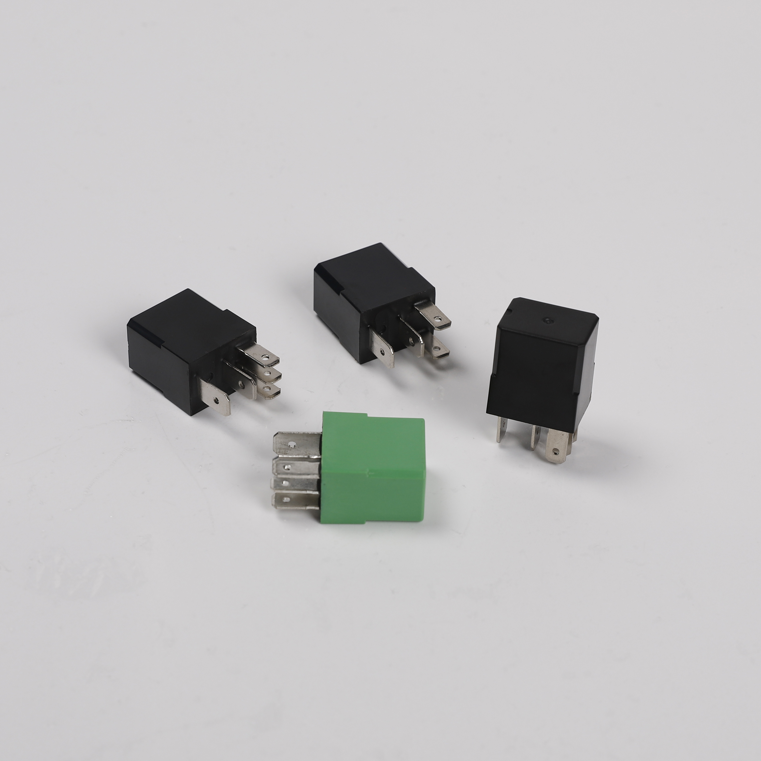
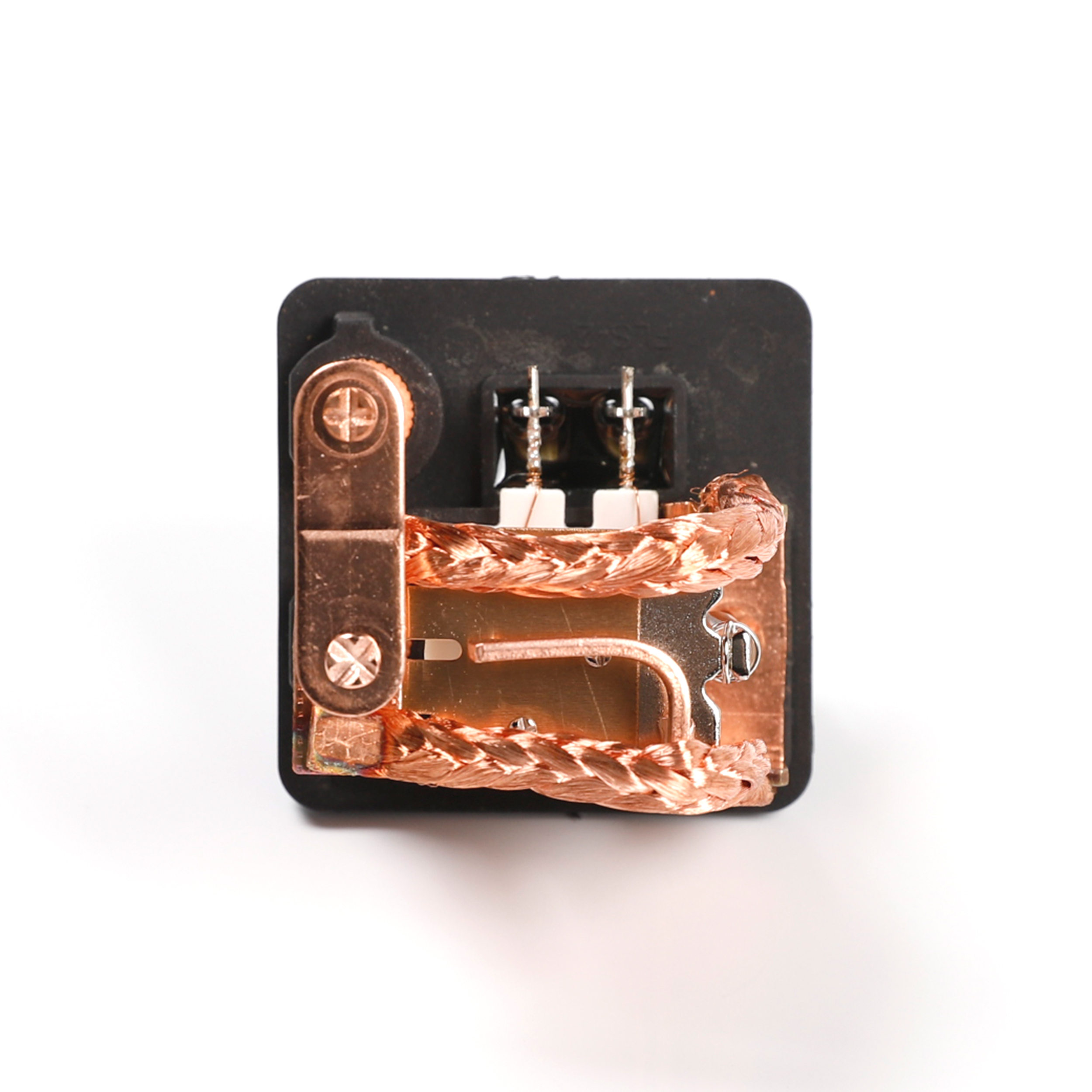
Examining an automotive relay diagram reveals its basic components: the coil, contacts, and housing. The coil serves as the control input, typically connected to a switch or electronic control unit (ECU). When energized, the coil generates a magnetic field, causing the contacts to close or open, thereby completing or interrupting the circuit to the load.
One of the primary advantages of relays is their versatility. They come in various configurations, including single pole single throw (SPST), single pole double throw (SPDT), and double pole double throw (DPDT), each tailored to specific applications. Understanding these configurations is crucial for accurately interpreting relay diagrams and troubleshooting electrical issues in vehicles.
In an SPST relay, there is only one set of contacts that either connects or disconnects the load from the power source. Conversely, an SPDT relay features a single set of moving contacts that can connect to either of two stationary contacts, allowing for dual functionality. DPDT relays, on the other hand, offer even more flexibility with two sets of moving contacts and multiple stationary contacts.
Translating a relay diagram into practical application requires meticulous attention to detail. Each relay pin serves a distinct purpose, from providing power to the coil to connecting to the load and ground. Understanding the pinout layout is essential for correct installation and troubleshooting.
| Serial Number | Product Name |
| 7 | Vehicle Relay |
Furthermore, automotive relay diagrams often include additional components such as Diodes, Resistors, and transient suppressors, which serve to protect the circuit from voltage spikes, electromagnetic interference, and reverse current flow. These components are strategically placed to ensure optimal performance and longevity of the relay and associated electrical systems.
Relays also play a vital role in automotive Safety and convenience features, such as headlights, Windshield Wipers, and power windows. By intelligently controlling these systems, relays enhance driver visibility, comfort, and overall vehicle performance.
In recent years, advancements in automotive technology have led to the integration of solid-state relays (SSRs) in place of traditional electromechanical relays. SSRs offer several benefits, including faster response times, lower power consumption, and greater reliability. However, understanding SSR diagrams requires a slightly different approach due to their semiconductor-based construction.
In conclusion, automotive relay diagrams serve as indispensable tools for understanding the intricate electrical systems that power modern vehicles. By unraveling the complexities of relay configurations, pinouts, and associated components, technicians and enthusiasts alike can gain a deeper appreciation for the role of relays in automotive engineering. Whether troubleshooting electrical issues or designing custom vehicle modifications, a comprehensive understanding of relay diagrams is essential for automotive enthusiasts and professionals alike.
| Number | Product Name |
| 6 | Automotive Relay |